Arduino Central
Design with the Arduino. Learn to program in C and C++ without getting overwhelmed
Wednesday, June 7, 2017
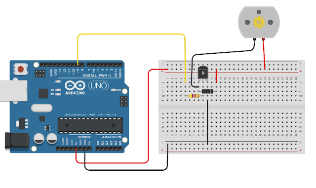
PWM Motor Drive
CODE FOR PWM DRIVE
int motor = 9;
int speed = 0;
void setup() {
pinMode(motor, OUTPUT);
}
void loop() {
analogWrite(motor, speed);
speed = speed + 31;
if (speed > 250)
{
speed = 255;
}
delay(4000);
if (speed > 250)
{
speed = 0;
}
}
Monday, June 5, 2017
Seven Segment Display Numbers
Code for driving segment display. To drive a common cathode the NOT operator ! must be removed from the front of the array in the highlighted part of the code.
//
make an array to save Sev Seg pin configuration of numbers
int
num_array[10][7] = { { 1,1,1,1,1,1,0
}, // 0
{ 0,1,1,0,0,0,0
}, // 1
{ 1,1,0,1,1,0,1
}, // 2
{ 1,1,1,1,0,0,1
}, // 3
{ 0,1,1,0,0,1,1
}, // 4
{ 1,0,1,1,0,1,1
}, // 5
{ 1,0,1,1,1,1,1
}, // 6
{ 1,1,1,0,0,0,0
}, // 7
{ 1,1,1,1,1,1,1
}, // 8
{ 1,1,1,0,0,1,1
}}; // 9
//function
header
void
Num_Write(int);
void
setup()
{
// set pin modes
pinMode(6, OUTPUT);
pinMode(7, OUTPUT);
pinMode(8, OUTPUT);
pinMode(9, OUTPUT);
pinMode(10, OUTPUT);
pinMode(11, OUTPUT);
pinMode(12, OUTPUT);
}
void
loop()
{
for (int counter = 10; counter > 0;
--counter)
{
delay(1000);
Num_Write(counter-1);
}
delay(5000);
}
//
this functions writes values to the sev seg pins
void
Num_Write(int number)
{
int pin= 6;
for (int j=0; j < 7; j++) {
digitalWrite(pin, !num_array[number][j]);
//Inverted array value due to Common Anode display
pin++;
}
}
Common Anode Seven-Segment Display Test
// 7 Segment test
void setup()
{
// define pin modes
pinMode(6,OUTPUT);
pinMode(7,OUTPUT);
pinMode(8,OUTPUT);
pinMode(9,OUTPUT);
pinMode(10,OUTPUT);
pinMode(11,OUTPUT);
pinMode(12,OUTPUT);
}
void loop()
{
for(int i=6;i<13;i++) //Clear LEDs since the outputs start LOW (LED ON)
{
digitalWrite(i,HIGH);
delay(1);
}
// loop to turn leds segments ON by sinking them (taking pins to GND)
for(int i=6;i<13;i++)
{
digitalWrite(i,LOW);
delay(600);
}
// loop to turn leds segnemts OFF by taking the pins to V+
for(int i=6;i<13;i++)
{
digitalWrite(i,HIGH);
delay(600);
}
delay(1000);
}
Tuesday, May 30, 2017
PWM Motor Control
PWM Motor Code
This code makes the motor speed up until it reaches the highest speed possible and then it resets to low speed again.
------------------------
int motor = 9;
int speed = 0;
void setup() {
pinMode(motor, OUTPUT);
}
void loop() {
analogWrite(motor, speed);
speed = speed + 31;
if (speed > 250)
{
speed = 255;
}
delay(4000);
if (speed > 250)
{
speed = 0;
}
}
Wednesday, May 24, 2017
Target Game
Hook up the following circuit starting with the servo first.
int sensorPin = A0;
int ledPin = 13;
int sensorValue;
#include <Servo.h>
Servo myservo;
void setup()
{
myservo.attach(9);
pinMode(ledPin, OUTPUT);
//Serial.begin(9600);
}
void loop()
{
sensorValue = analogRead(sensorPin);
//Serial.println(sensorValue); // Print value to monitor
analogWrite(ledPin, sensorValue);
if (sensorValue < 100)
{
myservo.write(180); // tell servo to go to position in variable 'pos'
delay(15);
}
else
{
myservo.write(90);
delay(2000);
}
}
Saturday, August 20, 2016
LED class with blink method
Below is a class I created to blink multiple LEDs at independent blink rates. This code below is the initial test of the class and shows you how to go about building a class of your own but you can save a lot of typing by downloading the library from Github using the following link:
led class code library
Just download led.cpp and led.h and put them in a library folder (call it led) where the Arduino libraries are located.
The code sample program is self explanintory. Just create an LED object using the following:
LED LED1 = LED(3); where 3 is the pin number you want to hook to the LED.
LED1.blink(100); Sets the blink rate of the LED to 100 milliseconds.
LED1.on(); Turns on the LED
LED1.off(); Turns off the LED
LED1.status(); Returns the status of the LED on or off
Have fun.
LED class and test of class ----------------------------------------------------------
class LED
{
public:
LED(int pin);
void on();
void off();
bool status();
void blink(int delayTime);
private:
int _pin;
bool _status;
int _delayTime;
int _rate;
unsigned long previousMillis = millis();
};
LED::LED(int pin)
{
_pin = pin;
pinMode(_pin,OUTPUT);
}
void LED::on()
{
digitalWrite(_pin, HIGH);
_status = 1;
}
void LED::off()
{
digitalWrite(_pin, LOW);
_status = 0;}
bool LED::status()
{
return _status;
}
void LED::blink(int delayTime)
{
_delayTime = delayTime;
if (millis() - previousMillis >= _delayTime) //if current system time - last time is greater then desired delay then make last system
// equal to current system time
{
previousMillis = millis();
if (_status == 0)
{
on();
}
else
{
off();
}
}
}
//Test of class --------------------
LED LED1 = LED(3);
LED LED2 = LED(4);
LED LED3 = LED(2);
void setup()
{
}
void loop()
{
LED1.blink(100);
LED2.blink(1000);
LED3.blink(500);
}
Thursday, August 11, 2016
Subscribe to:
Comments (Atom)


